")
")

SPEKTRORADIOMETRY


Badania radiometryczne uwzględniające rozkład spektralny
SPEKTRORADIOMETR
Radiometr mierzy całkowite promieniowanie elektromagnetyczne, podczas gdy spektroradiometr analizuje rozkład energii w zależności od długości fal, umożliwiając bardziej szczegółowe badania spektralne.
Radiometr:
Uwaga! Nie wszystkie radiometry są wykazane poniżej, tworzymy spektroradiometry/radiometry pod indywidualne zamówienia.
Spektroradiometr:
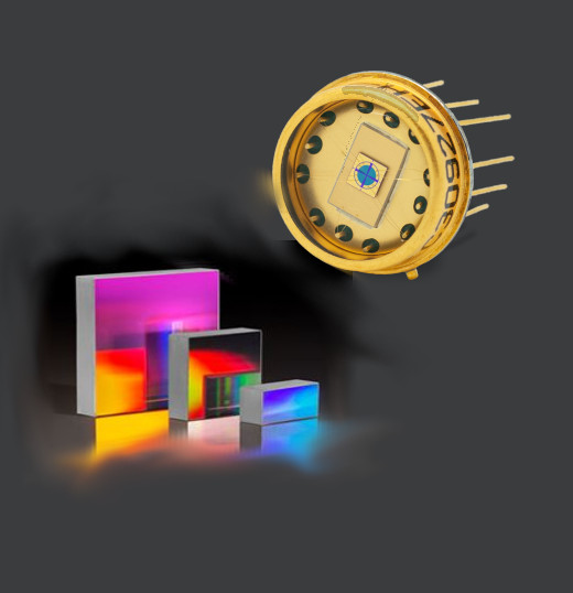
Spektroradiometr jest bardziej zaawansowanym narzędziem, które oprócz pomiaru całkowitej ilości energii promieniowania, jest również w stanie zbadać rozkład energii promieniowania w zależności od długości fal. Oznacza to, że spektroradiometr może mierzyć intensywność promieniowania w różnych pasmach widma. Może dostarczyć informacji na temat konkretnych długości fal lub widmowych charakterystyk promieniowania. Spektroradiometry są szeroko stosowane w badaniach naukowych, takich jak spektroskopia, analiza chemiczna, monitorowanie atmosferyczne itp.
| SERIA | ZAKRES | SZEROKOŚĆ |
| BTS2048-UV | 200-430 nm | 0,8 nm |
| BTS256-UV | 200-525 nm | 2,8 nm |
| BTS2048-UV-S | 200-550 nm | 1 nm |
| BTS2048-UVVISNIR | 200-900 nm | 2 nm |
| BTS2048-BS | 400-530 nm | 0,3 nm |
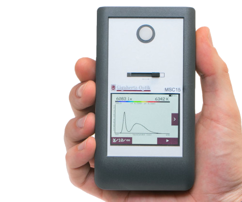
| CSS-45 & MSC15 | 360-830 nm | 10 nm |
| BTS256-LED | 360-830 nm | 5 nm |
| BTS256-EF | 360-830 nm | 10 nm |
| BTS2048-VL | 280-1050 nm | 2 nm |
| BTS2048-IR | 950-2150 nm | 9 nm |
Masz pytania?
Napisz do nas
Spektroradiometry dla zakresu UV-VIS-NIR
Pomiary radiometryczne w UV
- Wysoka redukcja światła rozproszonego (wersja BTS2048-UV-S ze zredukowanym filtrem)
- Ultraszybki interfejs i elektroniczna migawka
- Wysoka rozdzielczość optyczna
- Idealny do wszelkiego rodzaju zadań pomiarowych (LED UV, lampa deuterowa, lampa wolframowa do promieniowania słonecznego)
- Wysoka redukcja światła rozproszonego pomaga przenieść precyzyjną kalibrację na precyzyjne pomiary
UV optimized TE cooled CCD spectroradiometer with a wide dynamic range for CW and short-term measurement of the irradiance, spectrum, and peak wavelength. Accessories for other parameters.
Compact device. BiTec detector with back-thinned TE cooled CCD (2048 pixels, 0.8 nm optical resolution, electronic shutter), and SiC photodiode. Optical bandwidth correction (CIE214). Filter wheel with shutter and edge filter. Input lens with diffusor window. Cosine field of view.
Spectral: 3E-5 W/(m²nm) to 3E4 W/(m²nm) @325nm. Responsivity from 190 nm to 430 nm.
Integral: 2E5 W/m² to noise equivalent level by 5E-3 W/m²
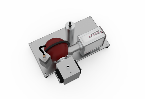
CCD spectroradiometer for design applications. Module for integration in test systems for front-end and back-end LED testing.
Factory calibration. Traceable to international calibration standards
PRODUCT
| Typical applications | Lightmeter for spectral Irradiance, Erythema, etc. | ||||||||||||
| Measured Quantity | Spectral irradiance (W/(m² nm)), irradiance (W/m²), peak wavelength, center wavelength, centroid wavelength, Erythema. Option integrating sphere: in addition spectral radiant power (W/nm) and radiant power (W) | ||||||||||||
| Input optics | Diffusor, cosine corrected field of view (f2 ≤ 3 %) | ||||||||||||
| Filter wheel | 4 positions (open, closed, optical filters). Use for remote dark current measurement and stray light reduction. | ||||||||||||
| BiTec | Parallel measurement with diode and array is possible, thereby linearity correction of the array through the diode and online correction of the spectral mismatch of the diode through a*(sz(λ)) respectively F*(sz(λ)). | ||||||||||||
| Calibration uncertainty | Spectral irradiance
| ||||||||||||
| Measurement modes | Standard measurement mode: 200 nm to 430 nm Out of Range stray light corrected measurement mode (OoR SLC): 200 nm to 430 nm Stray light corrected bandpass measurement mode (BP SLC): 300 nm to 386 nm |
SPECTRAL DETECTOR
| Integration Time | 2 μs - 60 s *1 It is recommended to perform a new dark signal measurement for every change in the integration time |
| Spectral range | (190 - 430) nm |
| Optical Bandwidth | 0.8 nm |
| Pixel resolution | ~0.13 nm/Pixel |
| Number of pixels | 2048 |
| Chip | Highly sensitive back-thinned CCD chip, one stage cooled (1TEC) |
| ADC | 16 bit (25 ns instruction cycle time) |
| Peak wavelength | ± 0.05 nm |
| Band-pass correction | mathematical online band-pass correction is supported |
| Linearity | completely linearized chip >99.6% |
| Peak wavelength | ± 0.05 nm |
| Stray Light | Out of Bound method < 1E-4 *3 typical value, measured 100 nm left of the peak of a cold white broadband LED with and deep blue LED peak |
| Base line noise | 5 cts *4 typical value measured without averaging for a 4ms measurement time and full scale control of the array. Averaging results in quadratic rise of the S/N i.e. quadratic fall of the base noise e.g. averaging to a factor 100 improves the S/N by a factor 10 |
| Peak wavelength | ± 0.05 nm |
| SNR | 5000 *5 typical value measured without averaging for a 4ms measurement time and full scale control of the array. Averaging results in quadratic rise of the S/N i.e. quadratic fall of the base noise e.g. averaging to a factor 100 improves the S/N by a factor 10 |
| Dynamic range | >9 Magnitudes |
| Spectral responsivity | (3E-5 - 3E4) W/(m²nm) @325nm *6 Minimum 500/1 S/N. Maximum at full scale control. *7 Irradiation only allowed for a short time so as to avoid thermal damage |
| Typical measurement time | W/m² of a Halogen lampe from (250 - 400) nm 1 : 4,4 s 10: 440 ms 100: 44 ms |
INTEGRAL DETECTOR
| Filter | Mathematical adjustment of the responsivity to a rectangular function from 220 nm to 360 nm (SMCF on-line correction to the radiometric function with the measured spectral data).* * The spectral responsitivity of the diode does not correspond to a rectangular function (not possible with optical filters). When measuring light sources with a spectrum that deviates from the calibration spectrum of the integral detector (UV LED, peak at 405 nm), the measurement result is corrected using SMCF. The uncertainty of this correction depends on the quality of the measured spectrum (noise) and the size of the correction factor (spectral range). |
| Measurement time | (0.1 - 6000) ms |
| Measurement range | seven (7) measurement ranges with transcendent offset correction |
| Calibration | Irradiance ± 6 % *10 Irradiation only allowed for a short time so as to avoid thermal damage |
| Measurement range | (5E-3 - 2E5) W/m² *11 By a spectral power distribution of a deuterium lamp, maximum radiation only allowed for a short time so as to avoid thermal damage |
| ADC | 16 bit |

32bit for device control,16bit for CCD array control, 8bit for photodiode control
USB V2.0, Ethernet (LAN UDP protocol), RS232, RS485
Standard for 2048 float array values via ethernet 7ms, via USB 2.0 140 ms
2x (0 - 25) VDC, 1x optocoupler isolated 5 V / 5 mA
2x open collector, max. 25 V, max. 500 mA
Trigger input incorporated (different options, rising/falling edge, delayed, etc.)
User software S-BTS2048
Optional software development kit S-SDK-BTS2048 for user software set-ups based on .dll‘s in C, C++,C# or in LabView.
With power supply: DC Input 5V (±10 %) at 700 mA
With USB bus (500mA) *8 during USB connection, not all functions are available due to the limited current supply e.g. no Ethernet and TEC cooling
103 mm x 107 mm x 52 mm (Length x Width x Height)
500 g
Tripod and M6 screw threads
Front adapter UMPA-1.0-HL for use with integrating sphere port-frame UMPF-1.0-HL
Storage: (-10 to 50) °C
Operation: (10 to 30) °C *9 Device required for temperature stabilization in approx. 25min. In measurement is performed in the warm-up phase, or if measurements are performed
under varying temperatures, dark signal measurement is required for each measurement
*2 typical value, the uncertainty of the dominant wavelength depends on the spectral distribution of the LED
Przykładowe zastosowania spektroradiometrów
Spektroradiometry są wykorzystywane m.im. do:
- do badania bezpieczeństwa fotobiologicznego
- do pomiarów źródeł światła takich jak diody LED i lasery
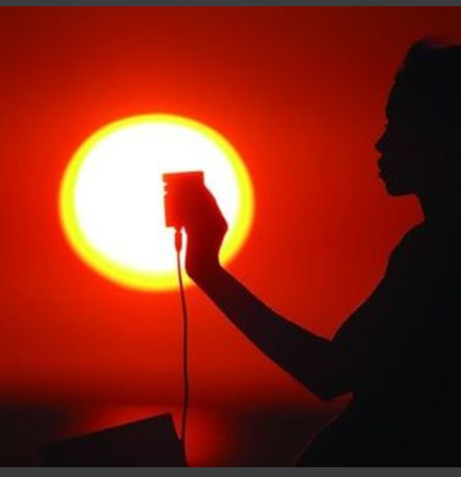
- do pomiarów promieniowania słonecznego naturalnego i sztucznego
- do badań procesu utwardzania UV
- do pomiarów fotometrycznych i kolorymetrycznych