IRED Axial Power Out Measurement
The on-axis power emitted by an IRED is measured by placing a detector, with a given active area, at some distance in front of the IRED and recording the average power falling upon the surface of that detector. The on-axis power is defined as an average power since more light might fall upon one portion of the detector than another.
For example, a silicon photodiode (For information on photodiodes and their characteristics, please Contact us) with Sr @ 880 nm = .5 A/W is being used to measure the on-axis power of a GaAlAs IRED. When a current meter is attached to the diode, a short circuit current, ISC, of 50 µA is read. On-Axis Power = 50 FA ÷ 0.5A/W = 100 µW Thus, 100 µW of power is incident on the photodiode. It might all fall on one portion or it might be evenly distributed over the entire surface of the detector.

On-Axis Power = 50 µA ÷ 0.5A/W = 100 µW
Thus, 100 µW of power is incident on the photodiode. It might all fall on one portion or it might be evenly distributed over the entire surface of the detector.
The measurement of on-axis power is informative and could be used to compare the output of IREDs in packages of the same lens type. However, it does nothing to help the designer who needs to know what their magnitude of output can be expected from a detector of a different active area and sensitivity positioned at different distances from the IRED.

To perform these calculations, the designer needs to know the on-axis power intensity of the IRED. The on-axis power intensity can be states as an irradiance, Ee (mW/cm2) or as a radiant intensity, Ie (mW/sr). We will deal with radiant intensity shortly, for the moment let’s study irradiance and how the diameter of the detector used and distance from the emitter to detector affects the detector.
The graph presented below illustrates the relationship between Ee and the size of the detector used to make the measurement. If the diameter of the detector is a good deal smaller than the distance between the detector and the IRED being measured, then Ee is independent of the size of the detector.

Irradiance vs. Diameter of Detector Used
In most practical cases, spacing (d) is much larger than detector diameter (D). The Ee obtained is then an accurate quantity, independent of the optical geometry and can be used to calculate the output signal for detector/IRED combinations.
Here is an example of such a calculation.
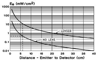
A silicon photodiode with an active area of .100" x .100" and an Sr @ 880 nm = 0.5 A/W is positioned 6 cm in front of a lensed IRED and then in front of an IRED with no focusing lens. The total power output of each IRED is identical. What is the output signal from the detector for both cases?

Irradiance vs. Distance - Emitter to Detector
From the graph, the Ee for both IRED/detector combinations can be found.
For the case of the lensed IRED: ISC = .5 A/W x .0645 cm2 x 11 mW/cm2 = 355 µA
For the case of the unlensed IRED: ISC = .5 A/W x .0645 cm2 x .44 mW/cm2 = 14.2 µA
In some cases the Irradiance vs. Distance curve may not provide data at the separation distance(s) of interest, or the curve itself may not be available. In such situations, if the irradiance is known at one distance of separation, Ee can be calculated by use of the inverse square law.
Ee @ d2 = Ee @ d1/[d2/d1]2
For example, let’s consider the output signal from the photodiode/lensed IRED pair used above when they are 30 cm apart.
Ee = 11 mW/cm2 / [30 cm / 6 cm]2 = .44 mW/cm2
ISC = .5 A/W x .0654 cm2 x .44 mW/cm2= 14.2 µA
Note: The inverse square law assumes that the light source (IRED) appears as a “point” source to the detector. In practical terms this means that the diameter of the light source is less than 1/10 the distance between the emitter and detector.
As already mentioned, on-axis power intensity can also be described in terms of radiant intensity, Ie. Radiant intensity defines on-axis power intensity as power per solid angle (mW/sr). The concept of a solid angle is described by the figure below.
A cone of a solid angle ω, has its apex at the center of a sphere of radius R and defines an area A, on that sphere as that
ω = A / R2 ≅ πr2 / R2 (sr)
The unit of measurement is the steradian (sr).

Example: A photodiode, with a circular active area .50 cm in diameter and sensitivity @ 880 nm of .5 A/W, is located 10 cm in front of a GaAlAs IRED whose Ie = 100 mW/sr. The value of the detector’s short circuit current can be calculated as:
ω = πr2 / R2 = π x (.50 cm / 2)2 / (10 cm)2 = .001963 (sr)
ISC = .5 A/W x 100 mW/sr x .001963 sr = 98.15 µA
Article based on Application Notes from Excelitas Technologies Photometric and Radiometric Terms application note
Usłyszane w sieci
Rzeczą ważniejszą od wiedzy jest wyobraźnia.
Albert Einstein


