Characterization of IRED Power Output
Almost all applications have an optical geometry containing a detector of a certain physical area that intercepts a portion of a “beam” of IR power emitted by the IRED.

This note explains the conceptual relationship between this basic geometry and several ways used to measure and sort IREDs in manufacturing.
Total Power Output:
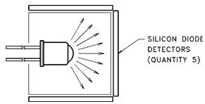
This is the quantity which is easiest to measure with a high degree of reproducibility. The measurement set-up consists of
some physical approximation to an integrating sphere. Nearly all of the power emitted by the IRED is collected and measured.
Advantages:
• Easy to get reproducible measurements
• Independent of optical irregularities in the IRED lens
• Independent of variations in mechanical positioning of the IRED under test.
Disadvantage:
• Total power output does not describe the beam pattern of the IRED (spatial distribution of emitted power). It provides incomplete information for the optical designer.

Wide Angle IRED
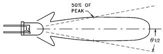
Narrow Angle IRED
Manufacturers commonly rate their IREDs by “power output” in milliwatts at a specified drive current. However, the specs will also include a “half power beam angle”, θ1/2. The half power beam angle can be used as a semi-quantitative guide to predict the behavior of the IRED in a given application. Within certain limits, “narrow angle” IREDs will contain more power in their “beam” than “wide angle” IREDs.
Radiant Intensity
Radiant intensity is defined as
Ie = ΔW/Δω
where:
ω = acceptance angle in steradians
and is normally applied to the “far field” radiation pattern where the IRED an be approximated as a point source of power
(viewing distance is at least ten times greater than the IRED lens diameter). Since it is defined in terms of power per solid angle, the radiant intensity is independent of the distance from the IRED.
In practice, the radiant intensity is measured by clamping the body of the IRED (thus establishing its “mechanical axis”) and measuring the output of a photodetector of diameter “D”. The solid angle is:
ω ≅ (π/4 D2 )/d2
and the IREDs are sorted into radiant intensity bins of “xx” mW/ sr.
It is important that the solid acceptance angle of the measuring apparatus be small enough to produce an essentially constant irradiance over the surface of the detector. Otherwise, different diameter detectors will produce different measured values of “radiant intensity”. Generally, the measuring solid angle is in the vicinity of 0.01 sr (steradians). Each manufacturer usually lists the steridian value of the test apparatus in the data sheet footnotes.
Advantages of Radiant Intensity Measurement:
• The designer can use Radiant Intensity quantitatively in many different design situations.
• IREDs which exceed a minimum Radiant Intensity value will usually show more consistent performance in the customer’s application.
Disadvantages of Radiant Intensity Measurement:
• It is hard to get highly reproducible measurements of Radiant Intensity. This is because it is difficult to establish the mechanical axis of the IRED reproducibly. The optical and mechanical axis of the IRED under test almost never coincide. The IRED bodies are tapered and never exactly circular. This leads to slight variations in the position of the IRED in the measuring apparatus each time it is measured.
Increased scatter in the measured values of Radiant Intensity is the result. In practice, Radiant Intensity is useful as a minimum specification only.
• Many applications of IREDs use a close spacing between the IRED and detector. Thus, Radiant Intensity — which is measured in the “far field” (spacing at least ten times IRED diameter) does not quantify the available power to be coupled from the IRED.
Irradiance:
Irradiance is defined by the power which passes through an aperture (usually circular, diameter D) which is spaced at a distance “d” from the tip of the IRED’s lens. Usually, both the aperture diameter “D” and the distance “d” are chosen to have values that are representative of many (but, unfortunately, not all) applications. Thus, Irradiance is a very practical—but geometry dependent—quantity. It should be noted that Irradiance has a precise mathematical definition in geometrical optics and is easy to calculate in the case of a sufficiently small diameter detector moved into the far field radiation pattern of the IRED.
Typical cone angles are in the range of 10 to 30 degrees. Larger cone angles give more reproducible measurements. However, larger cone angles reduce the absolute accuracy of the irradiance measurement since the radiant flux density (power density) emitted by the IRED is usually not constant over a large diameter.
Irradiance
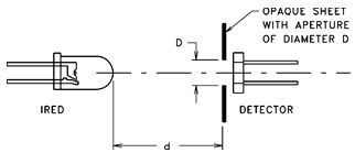
Equivalent to:
Irradiance can be calculated from the Radiant Intensity is the far field (d/D > 10) from the relationship:
Ee = Ie / d2
In summary:
Total Power Output is conventionally used throughout the industry to specify IREDs. It has the highest measurement reproducibility.
Radiant Intensity is useful as a far field (d/D > 10) specification but has no use close to the IRED lens. Radiant Intensity is hard to measure accurately because of difficulty in locating and clamping the mechanical axis of the IRED.
Irradiance is a useful measurement technique in the near field of the IRED’s beam pattern. Measuring the power through an aperture of diameter “D” spaced distance “d” from the IRED lens tip approximates many real-life application geometries. If the aperture “D” is large compared to the spacing “d” (large cone angle), the reproducibility of the irradiance measurement is improved, but, the absolute accuracy is decreased.
Article based on Application Notes from Excelitas Technologies Photometric and Radiometric Terms
Heard on the Internet
Imagination is more important than knowledge.
Albert Einstein


