Why F-Theta lenses are important in laser applications?
Article prepared based on our partner Excelitas Technologies documents
F-theta lenses are crucial in laser applications for several reasons:
-
Uniform Focus: In laser systems, maintaining a consistent focus across the entire scanning area is vital for accurate and precise results. F-theta lenses are designed specifically to provide a flat field of focus, ensuring that the laser beam remains uniform throughout the scanning process.
-
Aberration Correction: These lenses are optimized to minimize optical aberrations such as distortion and spherical aberration, which can otherwise degrade the quality of the laser beam. This correction capability is essential for achieving high-resolution and distortion-free laser imaging.
-
Speed and Efficiency: F-theta lenses enable rapid scanning speeds without sacrificing accuracy. Their design allows for fast beam deflection while maintaining precise focus, making them ideal for high-speed laser processing applications such as marking, engraving, and cutting.
-
Compatibility with Scanning Systems: F-theta lenses are specifically engineered to work seamlessly with laser scanning systems. They are designed to compensate for the angular dependence of the scanning beam, ensuring that the laser remains focused even as it moves across the scanning area.
Overall, F-theta lenses play a crucial role in laser applications where precision, speed, and consistency are paramount, making them indispensable tools in various industries such as manufacturing, medical, and research.
Linos F-Theta-Ronar lenses (as well as LINOS Focus-Ronar lenses, and LINOS Beam Expanders) are essential for top-notch laser material processing. They ensure optimal results across the entire working range, enhancing process safety, especially for challenging tasks. These tools find applications in various fields, including:
- Additive manufacturing (e.g., selective laser melting)
- Metal and non-ferrous metal welding (e.g., battery cell manufacturing)
- Metal and ceramic drilling and fineblanking (e.g., PCB micro drillings)
- Plastic welding for seamless connections without additional materials
- Structuring and perforating of metallic and non-metallic materials (e.g., solar cells, display glass)
- Labeling applications such as smart cards, ICs, printing plates, and keyboards
- Material-sparing cleaning in industrial and restoration projects (e.g., wafers, monuments)
- Consumer electronics and display manufacturing
- PCB production
Which F-Theta type is the best for my application?
Selecting the ideal f-theta lens is a critical step in optimizing laser systems for various applications. To ensure optimal performance, several factors must be considered:
- Material : Understanding your laser system's wavelength range is crucial for selecting the most suitable material.
To achieve desired optical properties Linos proposes two common materials like fused silica and ZnSe. Optical-glass lenses for all major applications can be proposed with various focal lengths ranging from100 mm to 420 mm and for different wavelengths from 532 nm to 1064 nm. Fused-silica lenses provide minimized thermal focus shiftand higher resistance when working at high powerdensity. These lenses are usable for wavelength rangesof 340-360 nm, 440-460 nm, 515-540 nm, 1030-1080 nm or 1900-2000 nm.
- Coatings : Specially developed coating achieves very low reflection and qualified absorption values. The optical designs minimize damage due to back reflections onto the scanning mirrors and internal reflections. Anti-reflective coatings tailored to the laser wavelength improve system performance, while protective coatings enhance durability against environmental factors and contaminants.
- Damage treshold: It's important to know laser system specification (ie. beam diameter and power) to ensure compatibility with the f-theta lens and to avoid damage.
- Focal Length and Spot Size: Combining working distance and spot size requirements to achieve the desired spot size on the target.
- Field Size: The required field size for your application is crucial to ensure the laser beam covers the entire scanning area without distortion.
How the LINOS F-Theta-Ronar lenses work?
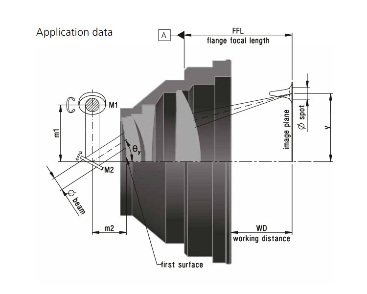
A collimated laser beam is deflected, for example by galvanometer mirrors, at an angle θ with respect to the optical axis. The LINOS F-Theta-Ronar lens focuses the ray bundels in its focal plane. By rotating the mirrors and thus changing the object angle θ, the focal point moves over the working plane.
F-Theta lenses have two main characteristics:
1. When a beam is deflected by a scanning mirror in front of a F-Theta lens, then the scanned distance is proportional to the scanning angle.
2. The focus position over the entire scan field is always in the same plane.
All LINOS F-Theta-Ronar lenses achieve diffraction limited performance. The truncated entrance beam diameter and the image spot diameter refer to the
intensity 1/e² at Gaussian illumination and for ideal M²=1.
The spot size of LINOS F-Theta-Ronar lenses can be calculated with the following formula:
Spot-Ø = 1.83 * λ * FL / beam-Ø
Spot-Ø: image spot diameter [μm]
1.83: factor of apodisation
λ: wavelength [nm]
FL: focal length [mm]
Beam-Ø: entrance-beam diameter [mm]
The scan length in each direction x or y can be calculated by the formula:
2y= FL * 2Θy * π/180 and 2x= FL * 2Θx * π/180
2x, 2y: scan length in direction x,y [mm]
FL: focal length [mm]
2Θx,y: max. scan angle Theta for each mirror [°]
π/180: conversion factor (into radians)
The mirror distances m1 and m2 are recommended values and may vary. A smaller entrance beam diameter allows larger scan angles and therefore larger scan fields are achievable.

The aperture stop position in the system is defined by the intersection of the chief ray of the incident beam bundle with the optical axis. For systems with a single scanning element, this position aligns with the scanning element. Ideally, the scanning element should be placed as close as possible to the first lens element of the objective lens. This minimizes the impact height of the beam on the lenses, reducing their diameters and overall size, resulting in a more compact lens design.
In systems with multiple scanning elements, such as scan heads, the aperture stop position varies for different scan angles. As most lens aberrations (excluding spherical aberration) depend on the aperture stop position, they fluctuate based on mirror deflection. Therefore, when designing the lens, it's crucial to know the number of scanning elements, their distances to each other (m1), and their distances to the lens (m2).
The design of scan heads significantly influences the field size and lens performance. Mirror distances (m1) vary depending on the aperture and model, affecting the aperture stop position. Additionally, scan heads have maximum deflection angles, usually limited by manufacturers to prevent mirror overexposure or collision. The distance between mirrors is termed as m1, while m2 represents the distance between the first lens surface's vertex and the center of the second scan head mirror.
For more information please ask our experts in SPECTROPOL or check our wide offer on F-Theta lenses


